Activity 2-6
[CA, CF, TL, N , IL]
Dimensioning
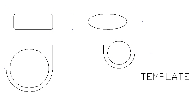
This activity will provide you with the opportunity to practice using several of the dimensioning tools discussed. You will be required to dimension the drawing assignment produced in Activity 2-5. If you no longer have a copy of that file, you will need to re-create that drawing.
Start AutoCAD 2000 LT and open the file "draw" (from Activity 2-5).
Then re-save the file as "dimension" inside your Unit2 folder.
You can remove the text "TEMPLATE" if it gets in the way of your dimension lines.
Next, I would like you to dimension the drawing exactly as follows:
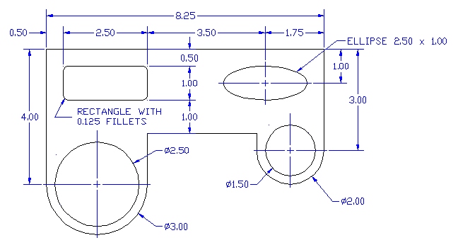
Before you start dimensioning, make sure you create a Dimension Layer. Set the Dimension Layer color to blue. You will also need to set the dimension properties using the Dimension Style window. Then, set the Dimension Layer to active and begin dimensioning.
Note: AutoCAD will not let you snap a center mark to an ellipse. You will need to build the center mark (for the ellipse) manually in the dimension layer using the line tool (see below).
Center Marks and Lines built
manually using the Line Tool.

I suggest setting your Snap X Y spacing to
0.125 when drawing the Center Mark and Lines.
All of your dimension lines must be laid out neatly and be a part of the dimension layer.
You will likely need to adjust your snap settings to lower values when creating some of the objects (i.e. the ellipse center mark).
Make sure the drawing is saved as "dimension" inside your Unit2 folder.