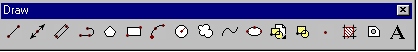
Draw
[CF, CA, T, B, N, CCT, TL]
| Line | Construction Line | Polygon | Rectangle | Arc |
| Circle | Ellipse | Point | Hatch | Text |
| Selecting, Editing and Deleting Objects | ||||
Create a new drawing.
AutoCAD drawings are made up of objects - lines, circles, polygons, and other geometric shapes that you use to create your final composition. Each object is an individual entity: that is, you can move, copy, resize, measure, and otherwise manipulate it separately from all the other objects in your drawing.
By default, objects are created using the property settings of the current layer. These properties are color, linetype, and lineweight.
Of the tools indicated above, we will be discussing the most common features of the following:
| Icon | Tool |
| Line | |
| Construction Line | |
| Polygon | |
| Rectangle | |
| Arc | |
| Circle | |
| Ellipse | |
| Point | |
| Hatch | |
| Multiline Text |
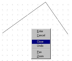
Right-Click Menus
The majority of tool items within AutoCAD have extended features. Some CAD applications have expandable toolbars that allow access to these features. In AutoCAD 2000 LT, these features are accessible by clicking the right mouse button (when a tool has been selected). The right mouse click is context sensitive. This means that the pop-up menu displayed on a right mouse click displays options available to the active tool. When no tools are selected, the pop-up menu displays options that pertain to the entire drawing area.
Note: to end/exit/or break out of a tool mode, press the Enter or Esc key. You can also end a mode by using your right click menus.
With line or ![]() , you can create a series
of line segments with each line segment behaving as a separate object. Each single
line segment can be edited separately from the other line segments in a series. You can
also close a sequence of line segments so that the first and last segments are joined.
, you can create a series
of line segments with each line segment behaving as a separate object. Each single
line segment can be edited separately from the other line segments in a series. You can
also close a sequence of line segments so that the first and last segments are joined.
When creating line segments, you can specify absolute or relative points using Cartesian (x, y) or polar (length<angle) coordinates on the command line or select points using your mouse. Remember to precede all relative coordinates with the @ symbol.
If you enter a relative coordinate first, the line is drawn relative to the last point selected.
Try drawing some lines inside your AutoCAD window using your mouse and manual coordinate entry. Try using the Close option to close the line sequence (you must have at least 2 line segments in a sequence before you can use the Close feature). Clear your drawing area when you are comfortable with this tool.
A construction line (xline or ![]() ) can be
placed anywhere in three-dimensional space. Construction lines extend into infinity (there
are no end points). You can specify its orientation in several ways. The default method
for creating the line is the two-point method: you specify two points to
define the orientation.
) can be
placed anywhere in three-dimensional space. Construction lines extend into infinity (there
are no end points). You can specify its orientation in several ways. The default method
for creating the line is the two-point method: you specify two points to
define the orientation.
Try drawing some construction lines (using the default two-point method) in your drawing area to see how they behave. Clear your drawing area when you are comfortable with this tool.
AutoCAD supports polygons (polygon or ![]() )between 3 and
1,024 equal-length sides. Creating polygons is a simple way to draw squares, equilateral
triangles, octagons, and so on.
)between 3 and
1,024 equal-length sides. Creating polygons is a simple way to draw squares, equilateral
triangles, octagons, and so on.
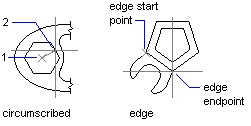
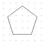
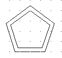
The illustrations below show polygons drawn using two different methods. In the method on the left, the center of the polygon and the radius length were specified with the pointing device. In the method on the right, the length of one edge determines the size of the polygon.
There are many ways to create polygons:
When creating polygons, you need to watch the command line for instructions.
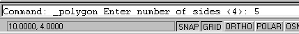
Let's try creating a 5 sided polygon with radius of 1 using the circumscribed method:
Specify the center of the polygon by entering the coordinate point (and then press the Enter key) or by selecting a point using your mouse.
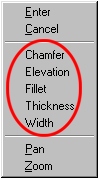
Note: The command line allows you the option to use the Edge method for constructing the polygon. To activate the Edge method, click your right mouse button and select Edge from the popup menu, or type edge on the command line. Also, when entering commands on the command line, it is usually not necessary to enter the entire command. You can usually get away with the first or first and second character of the command (e.g. E, e, ed, etc. would all be acceptable to launch the edge method).
![]()
Specify the Circumscribed method on the command line by entering C (and then press the Enter key) or right clicking and selecting Circumscribed about circle.
Note: the command line will default to the value set during last usage (default is indicated in between angle brackets (e.g. <C>).
![]()
Specify the radius of the circle by entering a value of 1 on the command line (and then press the Enter key). You can also specify the radius by selecting a point using your mouse.
Finished Polygon
Finally try creating a polygon using the Edge method.
Clear your drawing area when you are comfortable with this tool.
Rectangles (rectang or rectangle or ![]() )can
be constructed in one of two methods:
)can
be constructed in one of two methods:
In addition, drawing rectangles can include the following properties:
As in most tools, once a property has been changed, that tools properties are retained until the next change occurs. Lets start by initializing all the rectangle properties to 0.
![]()
You can adjust each of the indicated rectangle properties by typing in the first character of each property - c, e, f, t, w - (and then press the Enter key) or by clicking your right mouse button and selecting the property.
Set each of the rectangles properties to 0. Note: whenever you use a tool for the first time in a new drawing project, you should always make sure that its properties are initialized to the correct values.
Draw a rectangle somewhere in your drawing area (using the first and opposite corner method). You can use absolute, relative, Cartesian, or polar coordinate entry when specifying your points.
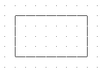
Draw a rectangle somewhere in your drawing area (using the Dimension method). When using the Dimension method you still need to select the initial corner with your mouse or by specifying a point on the command line. Then type d or click the right mouse button and select Dimensions. You will then be asked for the length, and width of the rectangle. When length and width are entered, you have the option to place the rectangle in one of four regions rotated about the initial corner (using your mouse).
![]()
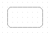
Draw another rectangle somewhere in your drawing area but this time set the Chamfer properties to 0.25 and 0.25.
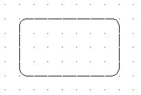
Reset the Chamfer properties back to 0 and then draw another rectangle somewhere in your drawing area with a Fillet radius of 0.25.
Clear your drawing area when you are comfortable with this tool.
You can create arcs (arc or ![]() ) in several
ways. With the exception of the first method described below, arcs are drawn
counterclockwise from the start point to the endpoint. In Drafting 10, we will only be
using the 3 methods described below.
) in several
ways. With the exception of the first method described below, arcs are drawn
counterclockwise from the start point to the endpoint. In Drafting 10, we will only be
using the 3 methods described below.
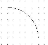
By default, arcs are drawn by specifying 3 points (start point, second point, and end point).
The arc tool also allows you to draw arcs by specifying the center point and then the start and end point. You will need to watch the command line for directions when using this method.
You can also draw arcs be specifying the center point and the included angle between the start and end points. To do this, start by specifying the center point, then the start point and then specify the included angle.
The above 3 methods are the most common. Feel free if you wish to explore the other methods.
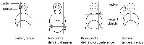
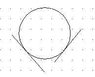
You can create circles (circle or ![]() )
in several ways. The default method is to specify the center and the radius. AutoCAD LT
provides three other ways to draw a circle, as shown in the illustration.
)
in several ways. The default method is to specify the center and the radius. AutoCAD LT
provides three other ways to draw a circle, as shown in the illustration.
![]()
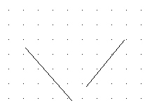
Then, draw the circle using the tangent, tangent, radius method. To do so, you will need to click on the two objects you wish to make the circle tangent to. Then enter the radius of the circle. The tangent, tangent, radius method is an important technique used in several of your drawing projects later on. Be sure you are comfortable with this method before moving on.
The drawing of ellipses (ellipse or ![]() ) is fairly
intuitive. There are two methods for drawing ellipses that you will be required to
perform:
) is fairly
intuitive. There are two methods for drawing ellipses that you will be required to
perform:
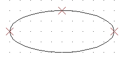
axis endpoint method
Try drawing some ellipses by specifying the center point and 2 axis endpoints.

center and 2 axis endpoint method
Clear your drawing area when you are comfortable with this tool.
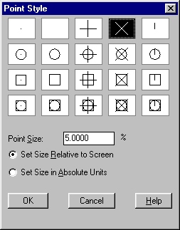
Point (point or ![]() ) objects are useful as
nodes or reference geometry when creating other objects. You can set the style of the
points and their size relative to the screen or in absolute units. Changing the style of
points makes them more visible and easier to differentiate from grid dots.
) objects are useful as
nodes or reference geometry when creating other objects. You can set the style of the
points and their size relative to the screen or in absolute units. Changing the style of
points makes them more visible and easier to differentiate from grid dots.
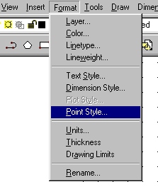
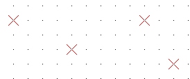
Select a point style you wish to use (I suggest choosing a style that contains a crosshair).
Next, select OK and then using the point tool, place points inside your drawing area.
Clear your drawing area when you are comfortable with this tool.
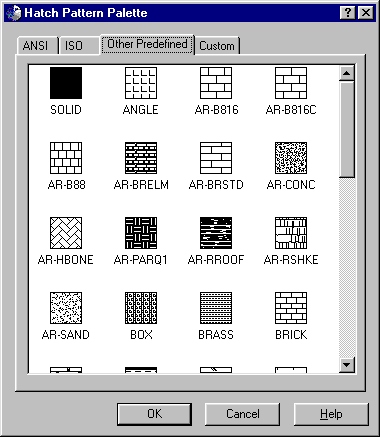
You can use several methods to add hatch (hatch or ![]() )
patterns to your drawing. AutoCAD LT supplies a solid fill and more than 50
industry-standard hatch patterns that you can use to differentiate the components of
objects or represent object materials.
)
patterns to your drawing. AutoCAD LT supplies a solid fill and more than 50
industry-standard hatch patterns that you can use to differentiate the components of
objects or represent object materials.
You can also define your own hatch pattern using the current linetype with the User Defined Pattern option, or you can create more complex hatch patterns.
Due to the many combinations of objects that can be hatched, editing hatched geometry can produce unexpected results. If you create a hatch that you don't want, you can undo it or you can delete the hatch block and re-hatch the area.
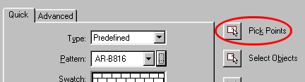
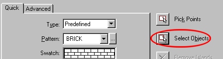
Select the Hatch tool. Make sure the Quick tab is selected and then select the button indicated below.
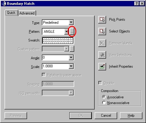
Browse through the various tabs and select a Hatch Pattern of your choice.
When done select OK. This will return you to the previous window.
Then select the Pick Points button.
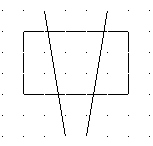
Using your mouse, click inside the following regions.
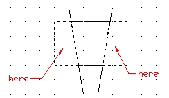
When done press the Enter key.
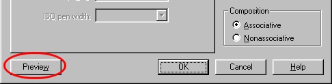
To preview how the hatch will look in your drawing, select the Preview button.
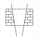
hatch preview
Note: if your hatch pattern is too small or too large (if it's too large, you may not even see the pattern in the preview window), you can adjust the scale size (smaller scale to make the pattern smaller and larger scale to make the pattern larger). If you need to return to the Hatch Edit window from preview mode, press the Enter key.
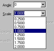
adjusting scale
Press the Enter key to return to the Hatch Edit window.
If you are comfortable with the Hatch, then select the OK button in the Hatch Edit window.
Note: to fill an entire object with a Hatch Pattern, you can use the Select Objects button instead of Pick Points.
Try creating a variety of Hatch Patterns in various objects. When you are comfortable using the Hatch tool, clear your drawing area.
The text you add to your drawings conveys a variety of information. It may be a complex specification, title block information, a label, or even part of the drawing.
Use single-line text to create one or more lines of text, ending each line when you press ENTER. Each text line is an independent object that you can relocate, reformat, or otherwise modify. The command for single-line text can only be reached from the command line (text) or from the Draw - Text - Single Line Text menu item. Single line text is created by specifying the start point, height of the text and then the rotation angle of the text.
Multi-line text (mtext or ![]() )
consists of any number of text lines or paragraphs that fit within a width you specify; it
can extend vertically to an indefinite length. Regardless of the number of lines, each set
of paragraphs created in a single editing session forms a single object,
which you can move, rotate, erase, copy, mirror, or scale. There are more editing options
for multiline text than there are for single-line text. For example, you can apply
underlining, fonts, color, and text height changes to individual characters, words, or
phrases within a paragraph.
)
consists of any number of text lines or paragraphs that fit within a width you specify; it
can extend vertically to an indefinite length. Regardless of the number of lines, each set
of paragraphs created in a single editing session forms a single object,
which you can move, rotate, erase, copy, mirror, or scale. There are more editing options
for multiline text than there are for single-line text. For example, you can apply
underlining, fonts, color, and text height changes to individual characters, words, or
phrases within a paragraph.
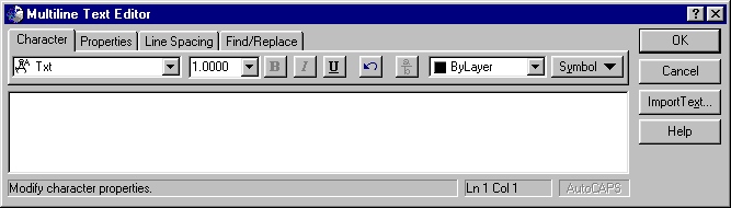
Multi-line text is created by specifying the starting corner and the opposite corner using your mouse or manual coordinate entry. After this, you will see the Multiline Text Editor window where you can enter and edit your text.
Try creating single-line text objects (text on the command line).
Try creating multi-line text objects.
Clear your drawing area when you are comfortable with these tools.
Selecting, Editing and Deleting Objects
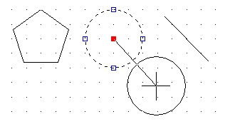
To select an object for editing or deletion, click on it once until you see handles appear on the object (see below).

Polygon, Circle, and Line Selected
At this point you could select the object(s) for deletion or you can grab one of the handles on the object to move or edit it. Depending on the type of object selected, different editing possibilities exist.
Objects such as circles, lines, and ellipses can be moved by grabbing them by their center handle.
To move an object, click once on its center handle and then move it to a new location and then click again. Press the Esc key when you are done editing an object.
To perform other editing options on objects, grab it using one of the other handles. Different editing behaviors exist depending on the object selected.
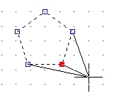 moving a node |
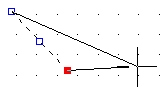 moving an end point |
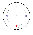 altering diameter |
You can also adjust the properties of any object by first selecting the object and then clicking the right mouse button and then select Properties.
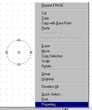
The following window appears:
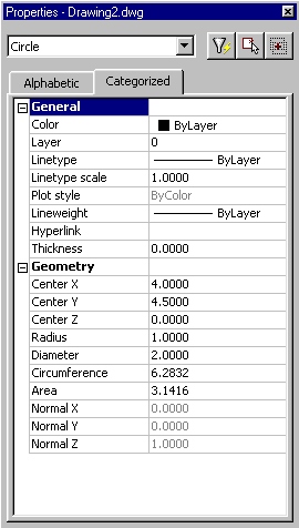
Again, depending on the object selected, different properties will appear. Inside the properties window you can change property values for the object.
Create several different kinds of objects in your drawing area and try editing them.
When you feel comfortable with this concept, clear your drawing area.
This ends the introduction to the drawing toolbar.
![]()