
Getting Started
[COM, TL, CF, CA, T]
Prelude
The next number of sections within this unit will be dedicated to introducing you to the user interface within AutoCAD 2000 LT. As stated previously, many of the tools and techniques to be demonstrated within this unit are common to many CAD software applications.
It is assumed that you have no previous experience using a CAD tool. Until you become familiar with this particular implementation of a CAD tool, it is highly recommended that you follow the instructions indicated explicitly. As we progress through this course, you will find that the specific instructions regarding the mechanics of CAD will diminish.
In other words, there will gradually be less emphasis on the mechanics of drawing and more emphasis on design concepts.
As your comfort level with this tool increases, the technology behind drawing creation will become second nature to you. Eventually, you will regard CAD as an invaluable tool in solving engineering design problems.
As we progress through the next number of sections, it is highly recommended that you keep this tutorial and AutoCAD open at all times. You will need to flip back and forth between windows as you progress through the balance of this unit. Do not progress to the next section until you understand the concepts and techniques discussed completely.
From this point forward, action oriented instructions specific to you will be indicated in blue. Explanations regarding the technique will remain in black text.
I would ask that you now start AutoCAD 2000 LT.
When AutoCAD starts, you will see the following window appear. In this course, we will only be using the tab selections circled in red. More specifically, we will use the window indicated to open and create new drawings.
Creating a New Drawing
Select the Create Drawings Tab.
Click on the dialog box to reveal the Wizards selection and then click on that.
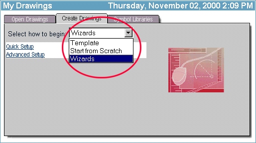
You will see the following options available:
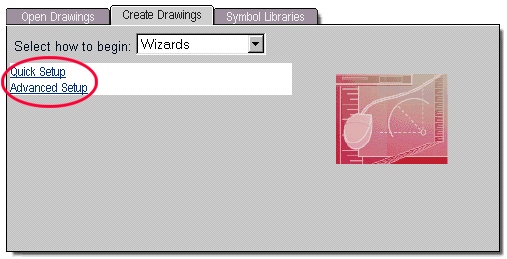
It is a matter of personal preference as to which setup you choose. Initially, I would like you to use Quick Setup for your drawings. I encourage you to explore the Advanced Setup later on in the course as you become comfortable with using this tool.
Select Quick Setup.
Units of Measurement
The first window allows you to specify the units of measurement. For all your drawing assignments, the drawing units you are to use will be specified.
Select each of the radio buttons to view how the indicated dimension changes. After you've done this, set the units to Decimal and then select Next.
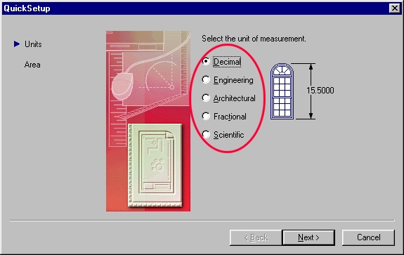
Unit Measure
Of the selections above, 3 are generic in nature (no units of measure) and 2 of them default to imperial units (i.e. feet and inches). A short description of each follows:
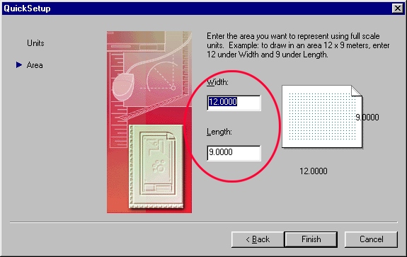
Drawing Area
This next window is used to set the Drawing Area for your drawing. In many CAD applications, it is extremely important that these settings be set properly. In the new releases of AutoCAD, drawing area setup is no longer as crucial as it once was. However, for many other CAD applications, setting the drawing area properly is an important step in ensuring that your drawing displays properly.
For this reason, a brief discussion of drawing area setup follows:
This setting can be somewhat misleading because CAD applications will let you draw outside the drawing area. This setting does not limit your physical drawing area. What it does do is:
Note: If you select Decimal, Fractional, or Scientific as the units, you cannot enter a unit of measure (i.e. feet, inches, cm, m, etc.) inside the Length or Width boxes. If you select Engineering or Architectural as the units, you must enter the feet ( ' ) and inches ( " ) symbol in the Length and Width boxes.
In CAD, drawing to scale is irrelevant. This might seem odd to people coming from manual drafting. All drawing done using CAD tools are done in real world units. Scaling is only a consideration when the drawing is actually printed.
Consider the following CAD drawing drawn in decimal units with a drawing area of 4 x 4.
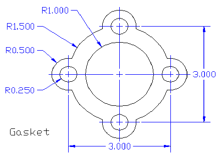 |
Drawn using AutoCAD 2000 LT. Notice that the dimension lines, text, and center line objects are proportional to the actual drawing. |
The overall length and width of this object is 4.000 x 4.000
distance between outside circles (center to center) = 3.000
+
radius of outer circles = 0.500 x 2 (one circle on each side)
=
4.000 total length and width
Notice that there is no mention of units (i.e. mm, inches, feet, etc.). This need not be considered when setting up the drawing area in Decimal, Fractional, or Scientific mode.
The vast majority of drawings do not include units of measure in the drawing area itself. They are indicated in the title block of the printed version (to be discussed later on in this unit).
As far as CAD is concerned, the only thing we need to be concerned about are the numerical units. Whether the above object has a width of 4 mm, 4 cm, 4 inches, 4 feet, 4 km, 4 miles is irrelevant at this point. The only thing that is important is that the object occupies an area of 4 x 4.
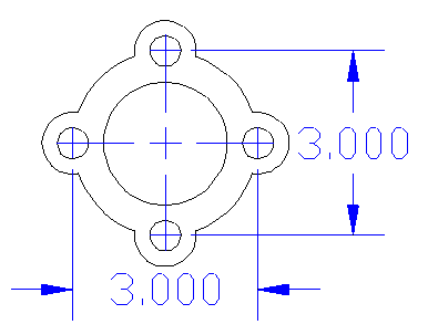
To demonstrate the importance of the drawing area setting, the same object indicated above will be recreated below with intentionally incorrect drawing areas.
Note: the 2 drawings below have been recreated with an older release of AutoCAD to demonstrate the importance of setting up the drawing area properly in some CAD applications. Newer releases of AutoCAD (such as AutoCAD 2000 LT) overcome this shortfall by defaulting all line, text, symbol, and dimension objects to an optimal scale.
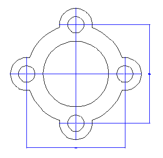 |
Drawing Area set too small. Notice that the dimensions are barely visible and the center marks have lost their detail. |
 |
Drawing Area Set too large. Notice that the dimensions given are too large in proportion to the drawing. In addition, the center marks do not display correctly. |
When entering the drawing area, the values entered need not be exact. They can be rounded up to the nearest whole unit.
| For example an object with: |
|
| Setting the drawing area to: |
|
is perfectly acceptable. |
|
If you are including several objects or views of an object on the same drawing, you will need to calculate the total width and length by adding all the lengths and widths to arrive at a total width and length. You can also take into account any empty space between views to accommodate for dimensioning. Remember that when entering drawing area, the values entered can be approximate whole units.
Set the Drawing Area settings to:
Then select Finish.
After the wizard exits, you should see the main AutoCAD window. If you see the Active Assistance window in the foreground, minimize it.
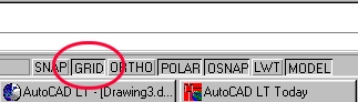
To display your working grid, click on the GRID button on the bottom center of your AutoCAD window.
You should then see the following in your drawing window. You may need to use your scroll bars to place your working grid in the center of the window.
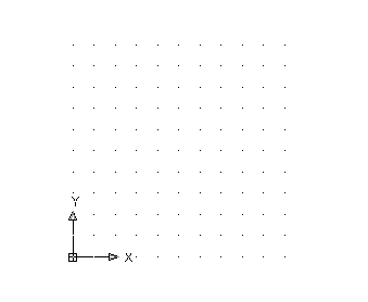
As you move your mouse around the drawing area, you will notice that the coordinate display (in the lower left corner of your AutoCAD window) changes.
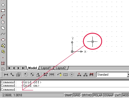
The two numbers in the coordinate display represent the x and y coordinates in real world units. Move your mouse to each corner of the displayed grid. You should find that the grid's size (not the number of dots) is exactly 5 x 5 units (coordinate display). The coordinate system and grid settings will be explained later on in this unit.
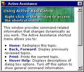
Active Assistance
New releases of AutoCAD have a context sensitive Active Assistance feature. After a typical installation, this feature is automatically set to activate whenever AutoCAD 2000 LT starts. Because everything you you will need to know to build your drawings will be provided to you within the context of these on-line resources, I suggest that you disable this feature from starting automatically.
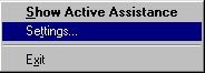
If you see the following icon on your taskbar when AutoCAD starts, then Active Assistance is set to start automatically.
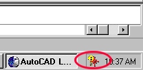
To disable this feature, right-click on the above icon and select the Settings option.
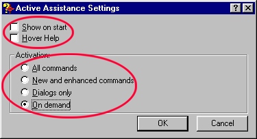
Next, de-select any options on the top part of the Active Assistance Settings window and then set Activation method to On demand. Then click on OK.
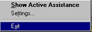
Finally, right-click on the Active Assistance icon (on the taskbar) and select Exit. This will close this portion of AutoCAD and remove it from your taskbar.
This concludes our study of the drawing Quick Setup Wizard.
You can now close the current drawing window (without saving).
![]()