Units: inches
Activity 4-1
(Guided)
[TL, T, CF, COM]
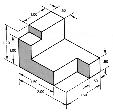
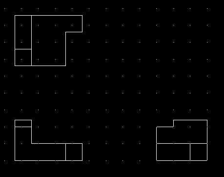
Create a 3 View (Front, Top & Right views) orthographic projection of the following object. In addition, create a layout (scale 1:1) with title block.
Units: inches
To help ease your transition into orthographic projection, I will guide you through this first drawing.
Because the drawing is in English units I suggest creating a new drawing from Scratch and selecting English (feet and inches). In other words, don't use the wizard.
Setting up the view locations and spacing at this point is a matter of personal preference. Some prefer to draw all the views and space them later using the move command. Remember that spacing between views need not be mathematically precise. Spacing using visual judgement is perfectly acceptable. However view alignment must be precise.
I will demonstrate setting up the location of each view mathematically right now.
I recommend always drawing a rough sketch indicating all views and their relation to each other before actually drawing anything in CAD. On this sketch you could include any calculations indicating view spacing.
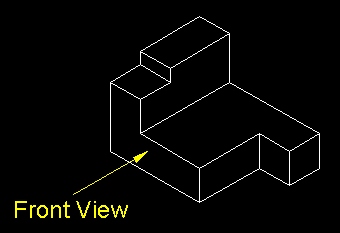
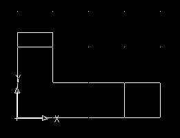
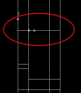
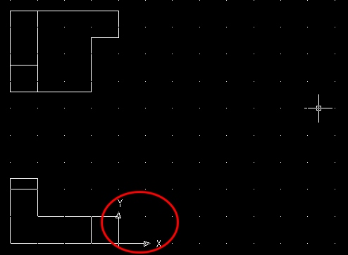
Before drawing a rough sketch, you need to determine which view will be the front view. Often the choice of front view is obvious. Other times you will need to make a judgement call. Let us assume a front view indicated by the arrow below.
Sketch with Spacing Calculations
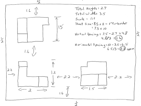
We will assume the drawing will be printed using a 1:1 scale on a sheet size of 8.5 x 11 inches.
Assuming a .5 inch border all the way around, this leaves us with a usable drawing area of 7.5 x 10 inches.
We then calculate the total width and height needed for views.
Then determine the total horizontal and vertical empty space left over.
Then determine the spacing between views (and borders and view).
Set your Snap and Grid to On.
Set your drawing limits (Format - Drawing Limits) to 10 x 7 (usable drawing area) using your mouse or coordinate entry. I suggest that you also set the UCS icon - On and Origin - On (View - Display - UCS Icon) .
Set your Snap and Grid settings to values comfortable for you. I've set my Snap spacing to 0.1 and left my Grid spacing to 0.5.
Next, set your origin to the bottom left corner of where the front view is to be located. We calculated this location to be 2.2 units to the right and 1.6 units up from the existing world UCS (2.2, 1.6). When you do this, you will notice the grid fill your entire screen and the UCS Icon will move to the new location.
Next, create a new layer and call it Object. Accept the default values for this layer and then set the Object layer to active.
I suggest zooming in by one factor before you start drawing.

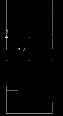
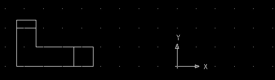
From the current UCS, assemble the front view of the drawing.
The view you choose to draw next is a matter of personal preference. I will now demonstrate constructing the top view.
Once the front view is drawn, the other views essentially construct themselves. I will demonstrate drawing the top view using the construction line method.
Start by re-positioning the origin to the top-left corner of the front view. Make sure your snap is turned on if you locate this point manually or use your snap to intersection to re-locate the origin.
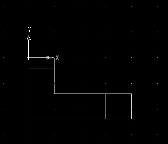
We now need to re-locate the origin again to the bottom-left corner of the top view. Earlier on we determined that the vertical spacing between views was to be 1.6 units.
Please re-locate the origin up exactly 1.6 units (0, 1.6).
Your next step is to use the existing vertical lines on the front
view to project vertical construction lines. Recall that
construction lines extend infinitely in opposite directions. You will be using your
construction line tool ![]() to perform this.
to perform this.
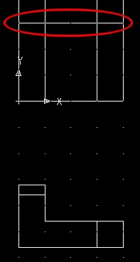
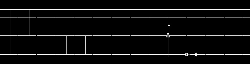
Select your construction line tool and draw construction lines using the existing vertical lines on the front view. If you don't have your snap to grid turned on, you will need to use your snap tools to locate 2 points directly on top the existing vertical lines.
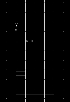
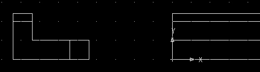
Next, draw a line from the origin and snap it (snap to perpendicular) to the construction line furthest to the right.
| Note: Throughout the balance of this guided activity, if you can confidently select points manually using the current snap and grid settings, then do so with care. Otherwise, I strongly encourage you to use your snap tools to locate points. Your course instructor(s) will not tolerate inaccuracy. There is no such thing as close in CAD. Drawing objects inaccurately placed will result in deductions in your project mark. |
The line created above is the bottom edge of the top view.
Next, trim away the construction lines beneath the horizontal line just drawn.
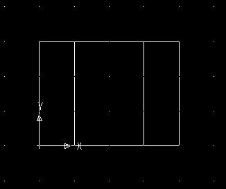
Let's now define the top edge of the top view. The height of the top view is 1.5 units.
Draw a horizontal line exactly 1.5 units above the bottom edge of the top view. Be precise. The line must touch the left and right edges of the top view. To do this you can relocate your origin up exactly 1.5 units and then draw the line. Or, you can build it manually using manual coordinate entry or carefully using your mouse (if your snap to grid is turned on).
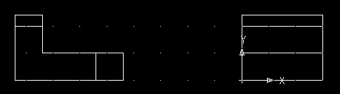
Next trim away the construction lines above the line just drawn.
Then insert the balance of the object lines and trim away any unnecessary lines (using the dimensions provided in the pictorial view at the top of this page).

We will now use the construction line method to build the third view (right view).
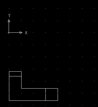
Start by re-positioning the origin to the bottom-right corner of the front view.
Then relocate your origin exactly 2.2 units (2.2, 0) to the right (horizontal spacing).
Select your construction line tool and draw construction lines using the existing horizontal lines on the front view.
Next, draw a line from the origin and snap it (snap to perpendicular) to the construction line furthest to the top.
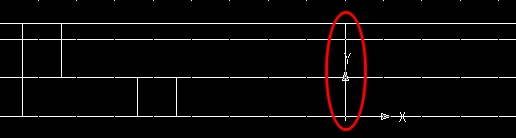
The line created above is the left edge of the right view.
Next, trim away the construction lines to the right of the vertical line just drawn.
Let's now define the right edge of the right view. The width of the right view is 1.5 units.
Draw a vertical line exactly 1.5 units to the right of the origin.
The line must touch the top and bottom edges of the right view.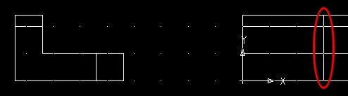
Next trim away the construction lines to the right of the line just drawn.
Then insert the balance of the object lines and trim away any unnecessary lines (using the dimensions provided in the pictorial view at the top of this page).

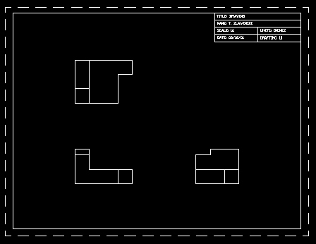
Your orthographic projection is now completed.
Next, create your layout (complete with title block). You may need to use the Plot Offset to center the drawing on your page.
Save the drawing as "mv1" (multiview) inside your Unit4 folder.