Dimension & Extension Lines
[CA, TL,CCT, CF]
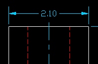
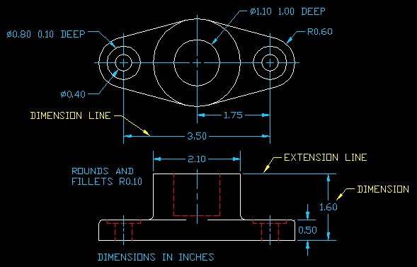
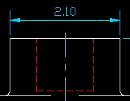
Dimension Lines - show the direction and extent of the numerical size. They are thin lines and terminate with an arrowhead at each end. A single style of arrowhead should be used throughout the drawing.
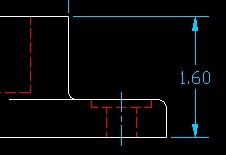
Extension Lines - are used to extend a surface or a point beyond the outline of the object so that a numerical size can be related to that surface. A small gap is left between the extension line and the outline to which it refers.
Dimension Placement
Normally, dimension lines should be broken for the insertion of the dimension that indicates the distance between the extension lines. An alternative (though not recommended) is to place the dimension above or to the outside of the dimension line.
|
|
 Not Recommended |
 Not Recommended |
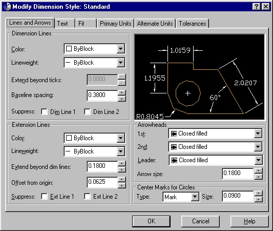
When adjusting formatting options for all dimensions in AutoCAD, use Format - Dimension Style - Modify.
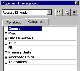
If you wish to adjust the formatting for a single dimension only, select the dimension with your left mouse button, and then right click anywhere on your screen and select Properties. You can then adjust the formatting for the specific dimension.
Dimension Spacing and Alignment
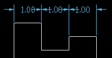
Dimensions that are consecutive must be aligned.
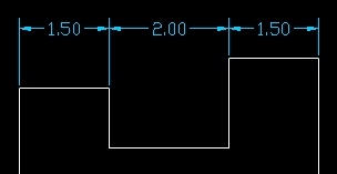
On occasion it is necessary to stagger parallel dimensions to avoid crowding.
 crowded dimensions |
 staggering prevents crowding |
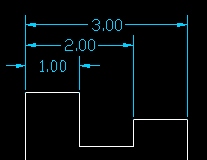
When staggering dimensions, place the shortest dimension closest to the outline.
shortest dimension closest to object
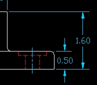
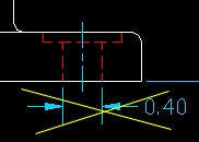
Avoid dimensioning to hidden lines unless it is absolutely necessary. Usually the hidden feature is visible (and can be dimensioned) in one of the other views.
Dimension lines should be placed outside the view whenever possible except when readability is improved by placing it inside the view.
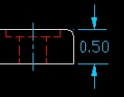 preferred |
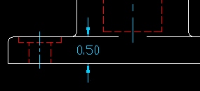 not recommended |
A small gap is left between the extension line and the outline to which it refers.
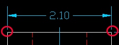
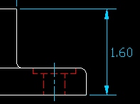
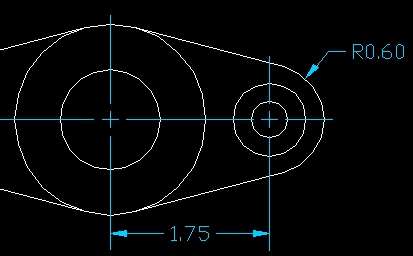
Center lines may be used as reference points when dimensioning to circular references. However, when you snap a dimension to the end point of a center line, you will notice small gaps in between the dimension and center lines (see below).
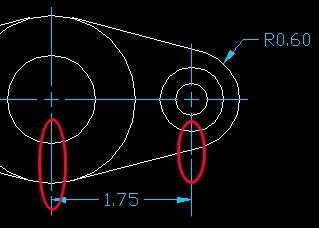
notice the gaps between lines
To fix this problem, select the affected center line with your mouse and then select the handle at the end of the center line and snap it to the endpoint of the extension line. Note: you may need to explode the center line using the explode tool before you can select the handle.
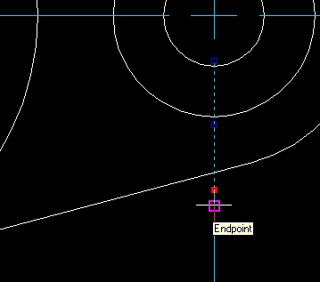
gaps properly filled
Angular Units
Angles should be measured in degrees. Generaly, angular dimensions should be placed off of the view except when readability is improved by placing it inside the view.
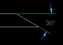
Dimension placed off the view
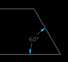
Sometimes placing dimensions in the
view improves readability. When doing
so make sure that the dimension does not
interfere with internal drawing detail.