Cutting plane lines are used to show the location of cutting planes for sectional views. There are two forms of cutting plane lines approved for engineering drawings.
The first form consists of evenly spaced dashes with arrowheads indicating the direction of sight.
The second form consists of alternating long dashes and pairs of short dashes.
On drawings that have a high density of line work, the cutting plane lines may be modified by omitting the dashes between the line ends for the purpose of obtaining clarity.
In either case, the lines should be drawn to stand out clearly on the drawing. The ends of the lines are bent at 90o and terminated by arrowheads.
Practice Activity
[IL, CCT, CA]
I strongly suggest that you open AutoCAD LT and try these practice activities before tackling the assigned activities for this unit. You may use English or metric units for these practice activities.
Sectional components (like other categories of drawing detail) should be drawn in their own layer (with their own color).
Create an object layer (default values) and a section layer (default values - except assign it a color different than the object layer).
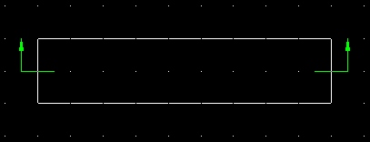
Create a rectangular object in your drawing area (size does not matter).
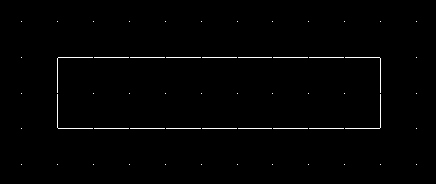
Let's assume we wish to create a cutting plane line horizontally through the center of the above object.
Make your section layer active.
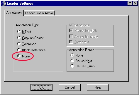
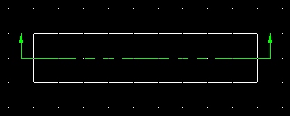
The leader tool is used to create the arrowheads. Before you can use the leader tool, you will need to change the leader settings. To do so, select the leader tool and then type an s or S (for settings) on the command line. Make sure the Annotation tab is selected and then check None under the Annotation Type section (see below).
Then snap a leader with a 90o angle to the midpoint of each end. I suggest using your current snap settings (you may need to adjust them - Tools - Drafting Settings).
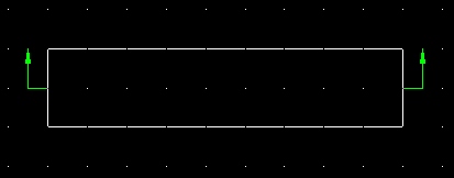
Use your judgement when locating cutting plane lines. You do not want the arrows too close or too far away from the object.
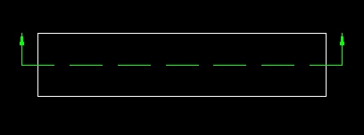
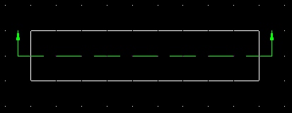
All we need to do now is fill in the middle portion of the cut plane line. Using the Object Properties toolbar, load the following line types:
Set the line type to Dashed and then snap a line between the two endpoints of the leaders drawn previously.
By default all line types are set to a scale of 1.0. If you find that the line detail is too small or too large, you can adjust the scale for the line by selecting the line with your mouse and then right-clicking anywhere on the screen (see below).
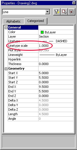
Decreasing the scale will make the line detail smaller. Increasing the scale will make the line detail larger.
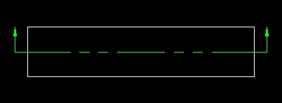
Next, try creating a cutting plane line using the other line type (Phantom). Again, you may need to scale the line so that it appears proportional to the size of the object.
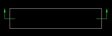
The last method of drawing cutting plane lines is used when there is a great deal of drawing detail within the object. Creating one of the standard two types of cutting plane lines would make the drawing confusing to the reader.
In this last method, snap a leader with a 90o angle to the midpoints of your object (as done previously).
Then select one of the leaders with your mouse. Then grab the handle on the endpoint and pull it inside of the object. Do the same to the other side. (see below)