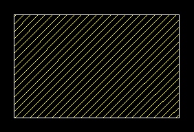
general purpose symbol for any material
Section lining, sometimes referred to as cross-hatching, is used to indicate material in the sectioned part.
Most often, the general purpose section lining symbol is used to represent any material. The exact type of material used to produce the object is usually given as a note somewhere else in the drawing. Section lining should be contained within the section layer and be the same color as the cutting plane lines.
general purpose symbol for any material
There are also several other types of section lining symbols used to represent a wide variety of materials. A few are illustrated below.
 Steel |
 Brick |
 Concrete |
In addition to the predefined section lining symbols, most CAD tools allow for the creation of custom section lines. Custom section lining allows the designer to create pictorially accurate representations of real features (such as siding on a house).
Practice Activity
[IL, CCT,
CA]
I strongly suggest that you open AutoCAD LT and practice using the hatching tool to fill a variety of different objects with different section line symbols.
Again, hatching (section lining) should be drawn in the section layer. When inserting section lining into an object, you will likely need to scale the symbols so that the hatching appears proportionate.
I suggest you review the section on hatching covered in the CAD Basics unit of this course.
Try creating several objects and filling those objects with various hatching symbols. Remember that hatching can only fill enclosed areas (make sure you have legal line intersections for all corners of the object you wish to fill.